Heat pump fault diagnosis starts with a clear description of the complaint and evidence from the complete system. Poor heating does not automatically mean low refrigerant. Airflow, water flow, heat emitters, controls, sensors and operating conditions can all affect performance. A useful investigation tests likely explanations before changing components or charge.
There are no universal fault codes or normal operating pressures for every heat pump. Use the correct service information for the model, refrigerant and operating mode. Refrigerant and electrical investigations must stay within the engineer's qualifications, competence and safe working arrangements.
Define the complaint before connecting instruments
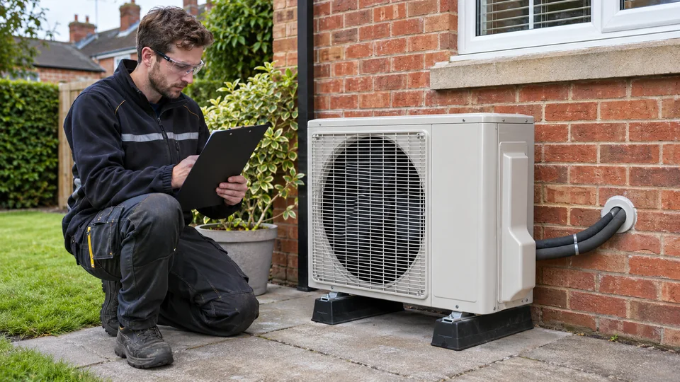
Ask what changed, when the issue occurs and how the customer operates the system. “Not heating” might mean a cold room, slow cylinder recovery, intermittent alarms or dissatisfaction with running cost. These are different starting points and may need different evidence.
Check the service history and original settings. Has a control been changed, an emitter removed or maintenance missed? Record the outdoor conditions and operating mode. A complaint that occurs only during a particular schedule or after an alteration may be explained without opening the refrigerant circuit.
Distinguish faults from expected behaviour
Heat pumps modulate and may interrupt heating for defrost or hot-water priority. Their behaviour is not identical to a boiler or a fixed-output cooling system. Explain normal operation only after checking that the frequency and duration of events are reasonable for the equipment and conditions.
Do not dismiss every report of frost as normal defrost. An obstructed coil, fan problem, drainage issue or control fault may need attention. Observe the sequence and consult the manufacturer's criteria. Record what happens rather than diagnosing from a photograph of ice alone.
Check airflow and heat transfer
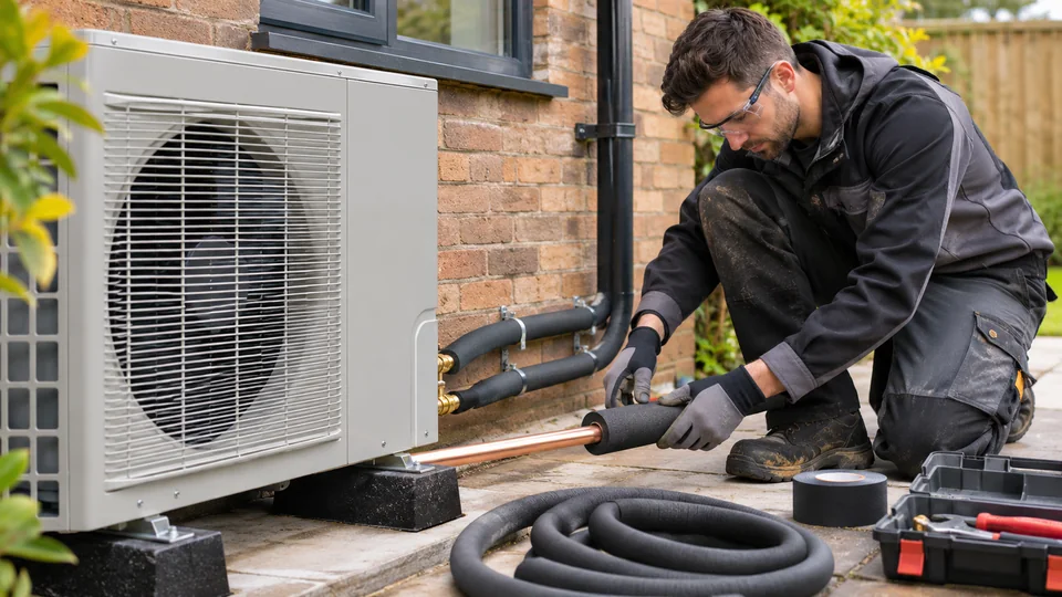
Inspect accessible coils, filters, fans and clearances as applicable. Blocked airflow reduces heat exchange and can influence temperatures, pressures and protection events. Correcting an airflow restriction is different from changing refrigerant charge, even where the instrument readings initially suggest a refrigerant-side symptom.
On air-to-water equipment, examine the heating-water side with the responsible competent person. Flow restrictions, air, closed valves, dirty strainers or pump issues can affect heat transfer. The system design and manufacturer's required flow conditions matter; a single temperature difference does not establish that every hydraulic condition is satisfactory.
Follow the controls and sensors
Confirm that the controller is actually requesting the expected operation. Review schedules, mode selection, setpoints, external inputs and any weather-compensation settings. A system can correctly obey an unsuitable setting and still disappoint the customer.
Sensor readings should be checked against the service procedure and suitable independent measurements where appropriate. Position, contact, wiring and configuration can influence the displayed value. Do not replace a sensor solely because its reading differs from a measurement taken at another location under different conditions.
Interpret refrigerant evidence in context
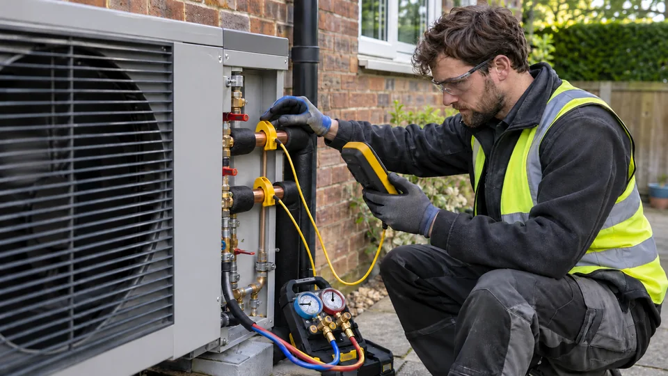
Pressure measurements need the refrigerant identity, operating mode, load, control state and corresponding temperatures. Inverter operation and expansion control can change the relationship between a snapshot and system condition. Use the manufacturer's diagnostic method, not a pressure remembered from another model.
Where superheat or subcooling assessment is relevant, correct measurement location and refrigerant data are essential. A charge decision should follow the specified method and investigation, not an isolated gauge reading. If a leak is suspected, address the cause and required checks rather than repeatedly topping up.
Installation history can change the investigation
A newly installed system with unsatisfactory performance raises questions about model matching, pipework, charge calculations and commissioning evidence. A previously reliable system that has deteriorated suggests a different history. Neither pattern proves a diagnosis, but both help prioritise checks.
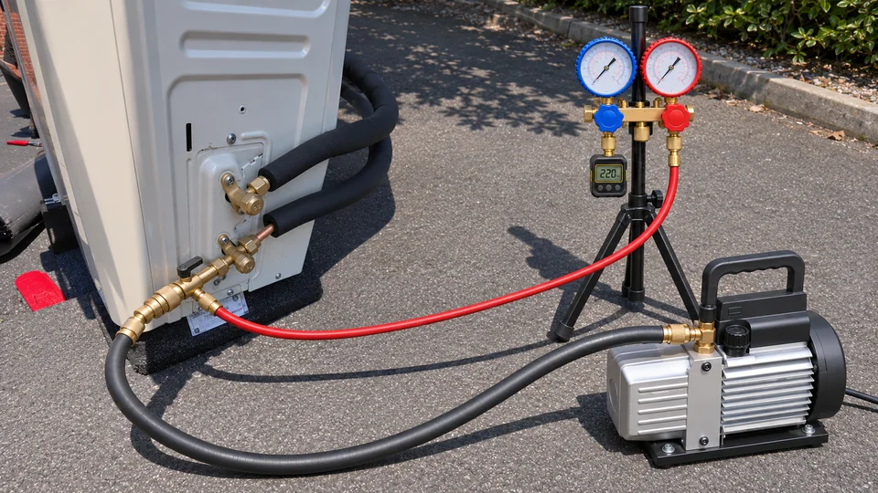
Review the commissioning checklist and actual records. If evacuation quality is in doubt, vacuum diagnostic principles explain relevant limitations, but opening a circuit simply to test a suspicion may create additional work and risk. Establish a justified plan first.
Common diagnostic mistakes
Changing several settings together makes it difficult to identify the cause. Replacing a component from an error-code label without following the diagnostic tree can miss a wiring or operating issue. Assuming a clean-looking outdoor unit guarantees satisfactory heat transfer overlooks internal and water-side conditions.
Another mistake is accepting a repair because the alarm cleared once. Repeat the relevant checks under appropriate conditions, confirm that the original complaint is addressed and restore any temporary test settings. Record any conditions that prevented complete verification and arrange follow-up where needed.
Work safely and preserve evidence
Electrical equipment, moving fans, pressure, hot surfaces and refrigerant hazards require suitable control measures. Use safe isolation where required and follow the prescribed test procedure. Do not bypass protective devices to keep a system running for convenience.
Keep an investigation record: complaint, conditions, observations, measured values, changes and the reason for the final diagnosis. That makes the next visit more productive and helps explain the outcome to the customer. For installation context, see preparing for a first split heat pump.
F-Gas 1's practical coaching can support qualified engineers in developing a systematic fault-finding method. Equipment-specific safety and diagnostic instructions remain essential; obtain the manufacturer's current service documentation rather than applying a generic chart to every machine.